APPLICATION
HARDWARE
In manufacturing our matching networks, we make no compromises with regards to quality and reliability. Top of the line ceramic and vacuum capacitors, as well as, silver-plated conductive components at high load locations guarantee high operating reliability and reproducibility. The case is manufactured of aluminum and all covers have copper-beryllium spring contact strips. This facilitates high-grade RF radiation shielding and accessibility, by the usage of just a few quick release closures to remove the covers.
MEASURING TECHNIQUES
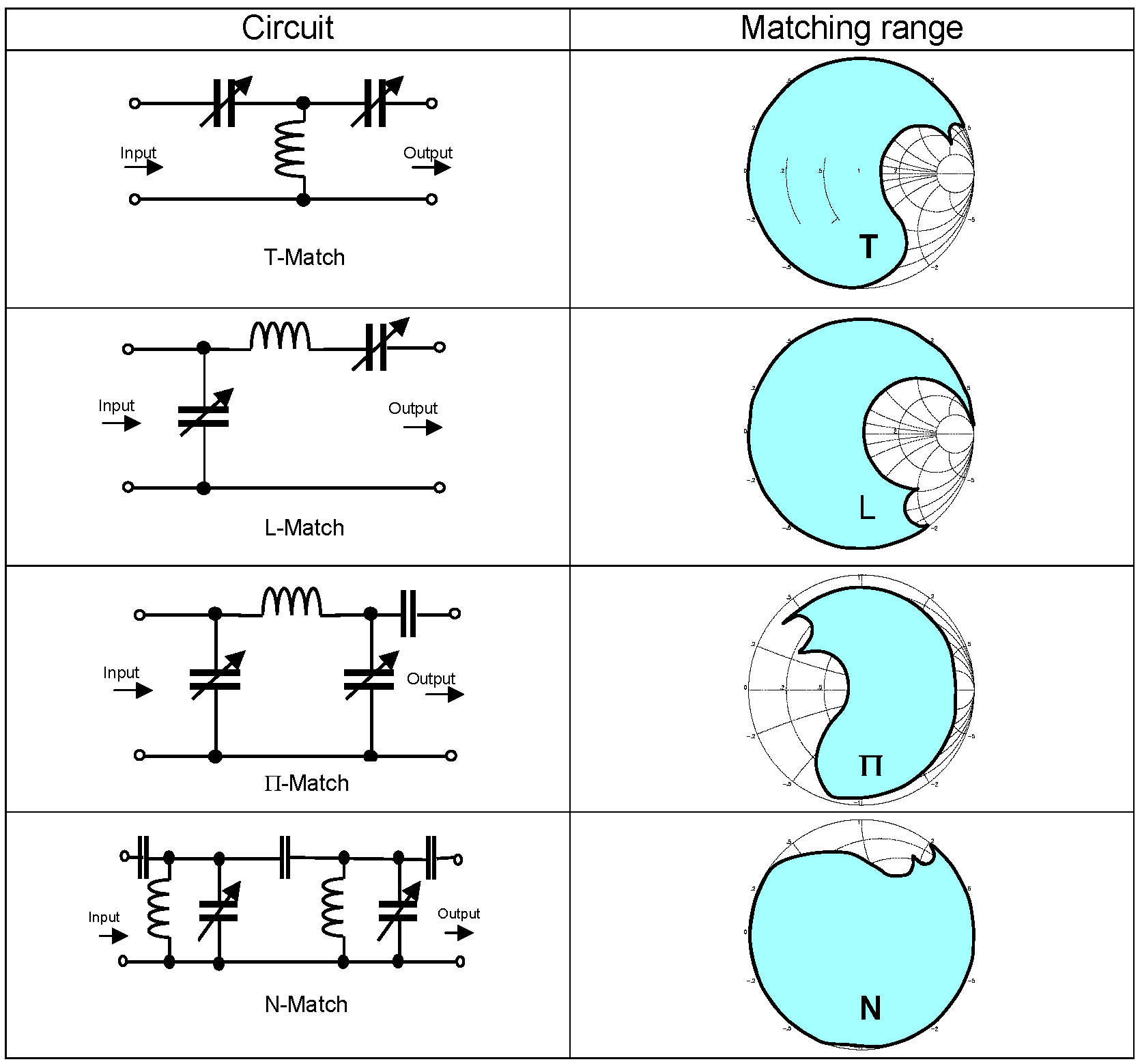
Via capacitive voltage dividers, two voltages are measured at a fixed capacitor at the input of the matchbox. These voltage dividers are designed to be low-coupling; thus, crosstalk is is suppressed.Currents are calculated from the voltage differences; direct current measurements with inductive couplers used by other manufacturers, which are susceptible to errors, are eliminated.The detected values are registered by a logarithmic amplifier. This technology permits very high precision and maximum companding. Figure 1 to the right, shows our typical circuits and their matching ranges as we design matching networks based on the requirements of the customers system.
The data measured is used to calculate input impedance and, with precision, the load impedance. From these figures, the controller determines the ideal set-up of the variable capacitors. Input and load impedance can be noted or processed further via system control.
Also, the DC bias potential is measured at the output of the matchbox and a plasma detector recognizes whether the plasma has ignited or not.
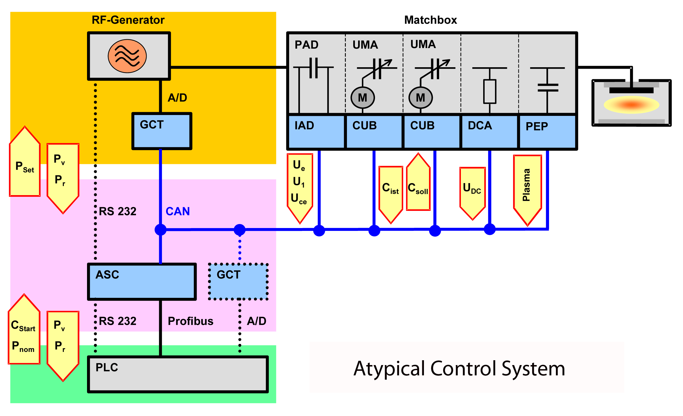
Our innovative sensor technology and modern CAN-Bus technology provides very localized intelligence.
The measured signals are A/D-converted immediately after their read and then transferred digitally – thus loss-free and stable against any potential electromagnetic interference – via the bus.
The motor drives of the vacuum capacitors are also equipped with their own set of electronics (CUB) including motor drivers, position registration and the CAN interface. Communication with the central controller uses direct pF gauging. Thus, a complete, pre-adjusted capacitor unit, including the driving mechanism, can be replaced without requiring any line-up activities. All process parameters are directly reproducible.
The central controller, ASC, has a standard equipment consisting of the CAN-Bus, an RS 232 interface and a Profibus.
A universal analog/digital interface card (GCT) is available for the integration of an RF generator. Via this card, the ASC can assume complete control of the RF generator, thus permitting the drive of the entire RF system including a non-profibus-compatible generator via the Profibus interface of the ASC.
As already mentioned, for autotuning, 2 voltages are measured at the fixed capacitor at the input. This figure is then used to calculate the input impedance, which then, with precision, establishes output or load impedance. As an option, the output impedance can be directly detected and then used to regulate the power exactly.
By means of the load impedance, it is possible to determine the reactive power, the output current and other process relevant parameters.
Those can be checked and indicated by the ETHOS configuration software or processed further via the control system.
Furthermore the output current can be limited in order to save the equipment.
Complete modularization permits quick and flexible control and with the software support adapted to the controls it can meet all kinds of different demands. For example, software variants are available for quick cycle time operations with sputtering times of merely seconds. Here, classical and currently available market leading companies’ auto-tuning would not be applicable.


